8 Results
View results:
Sort by:

The Steel Joist Institute (SJI) previously developed Virtual Joist tables to estimate the section properties for Open Web Steel Joists. These Virtual Joist sections are characterized as equivalent wide-flange beams which closely approximate the joist chord area, effective moment of inertia, and weight. Virtual Joists are also available in the RFEM and RSTAB cross-section database.

Slender bending beams that have a large h/w ratio and are loaded parallel to the minor axis tend to have stability issues. This is due to the deflection of the compression chord.

A site joint consisting of hollow sections with end plates will be designed. It is the bottom chord of a truss that has to be divided for transport reasons.

In SHAPE-THIN, the calculation of stiffened buckling panels can be performed according to Section 4.5 of EN 1993-1-5. For stiffened buckling panels, the effective surfaces due to local buckling of the single panels in the plate and in the stiffeners, as well as the effective surfaces from the entire panel buckling of the stiffened entire panel, have to be considered.
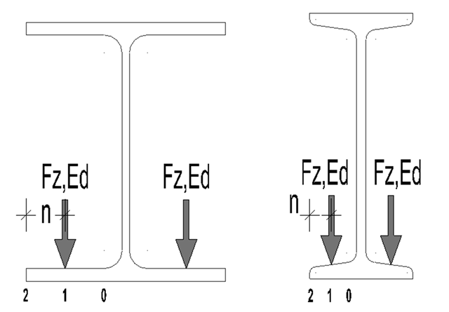
For suspension cranes, the bottom chord of the runway girder is subjected to local flange bending due to the wheel loads in addition to the main load-bearing capacity. The bottom chord behaves like a slab due to these local bending stresses, and has a biaxial stress condition [1].
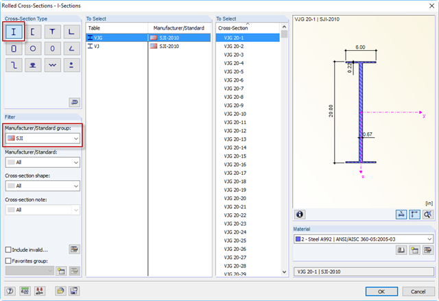
The Steel Joist Institute (SJI) previously developed Virtual Joist tables to estimate the section properties for Open Web Steel Joists. These Virtual Joist sections are characterized as equivalent wide-flange beams which closely approximate the joist chord area, effective moment of inertia, and weight. Virtual Joists are also available in the RFEM and RSTAB cross-section database.
![Formula Symbols for Connection Between Chords and Web (Source: [1])](/en/webimage/009346/2418256/01-en-3-png.png?mw=640&hash=7a1bc6e87da6f5aeb6d26a130c6ca3dfb6edb8a4)
In order to ensure the effects of panels, which should act as tensile or compression chords, it is necessary to connect them to the web in a shear-resistant manner. This connection is obtained in a similar way as the shear transfer in the joint between concreting sections by using the interaction between compressive struts and ties. In order to ensure the shear resistance, it must be verified that the compressive strut resistance is given and the tie force can be absorbed by the transverse reinforcement.
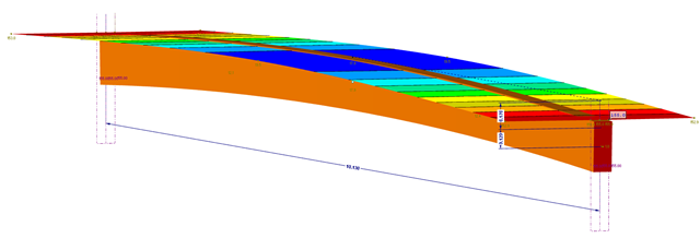
This part explains the determination of forces arising when screwing a straight cross-laminated timber plate to a curved glulam beam. For this, a glulam beam with a curved member was modeled in RFEM. The member has a precamber of 12 cm, since the preliminary design showed that the applied precamber of 6 cm will never be sufficient to maintain l/300. The dimensions of the bottom chord are 12 cm wide by 32 cm high. The plate was selected in RF‑LAMINATE as a three‑layer plate with a thickness of 8 cm.